
Vulcan Reference Manual

  • Welcome to Vulcan
  • Features
  • Production Workflow
    • Preparation
    • Jogging and Homing
    • Create
    • File Management
    • Select Program
    • Edit NC Code
    • Edit Laser Technology
    • Edit layout
    • Simulation run
    • Work offsets
    • Run
    • Re-entry
  • Laser Technology Tables (LTT)
    • Terminology
    • Laser Data items
      • Piercing
      • Multistage Piercing
      • Cutting
      • Special Processes
    • Modifying Laser Data
    • LTT Management
    • Ramp Cycles
    • FlyCut
    • Acceleration while cutting (DCA)
  • Technology functions
    • Vaporize Sheet
    • Nanojoints
    • PierceLine Sensor
    • Frog Jumping
    • Analog Gas Calibration
    • Cutting Tools
    • Dynamic Focus Control (DFC)
  • Control Elements
    • Lubrication Cycle
    • Protective Glass Monitoring
    • Scrap Cut
    • Go To Sheet Origin
    • Height Sensor Calibration
    • Nozzle Centre
    • Target Shot
    • Gas Purge
    • HC Manual Set Point
    • Go To Park Position
    • Nozzle Clean & Height Sensor Calibration
    • Edge Detection
    • Focus Comb
    • Focal Distance
    • Pilot Diode Positioning
  • Production plan
    • Create a production plan
    • Modification
    • Run a production plan
    • Running sequence
    • sheet loading
    • Material stock
  • Advanced functionality
    • Nozzle Changer
    • Pallet changer settings
    • Status light
    • Suction cup layout
    • Automation Interface
    • KL59, Laser & Optics
    • Automated corner optimization
  • Programming manual
    • DIN Programming
    • LST Programming
  • Machine configuration
    • Laser database
    • Work offsets
    • Machine settings
  • Experimental features
    • Camera based Nozzle Centering
    • Automated Focus Comb
    • Camera based part placement
    • High Power Options
    • Direct connection to Praxis
  • Service settings
    • General settings
      • Log files
      • Backup settings
    • Calibration of the pilot laser
    • Service settings
    • PLC functions for service's maintenance/ repair work for KL59
    • DCA settings
    • Info messages
  • Troubleshooting
    • Installation
    • Work offset
    • Error data, backup, restore
    • Frequent collisions
    • Laser issues
    • extreme small contours
Technology functions
/
Analog Gas Calibration

Analog Gas Calibration

If you want to use a proportional valve with analog DC 0-10v control for air pressure, you need to use air pressure calibration where the proportional valve air pressure feedback is a DC Voltage.

Steps to follow:

  1. Gas Configuration, Select the gas config of the machine.
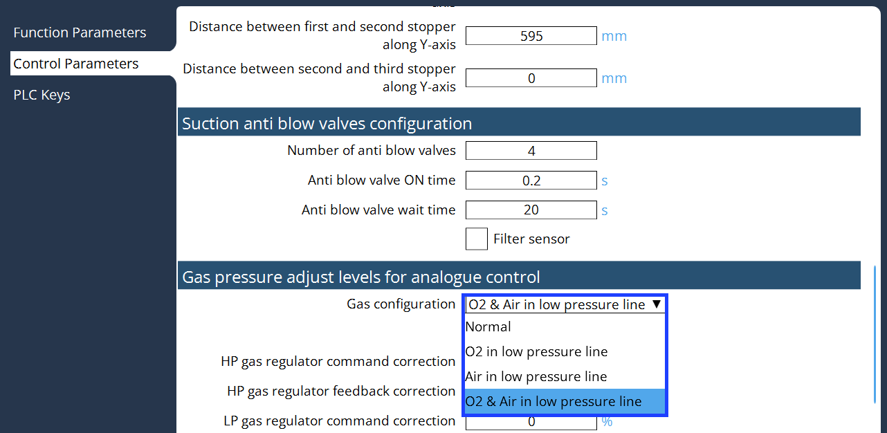
    gas1
  1. Select the calibration for the analogue control of pressure valve.
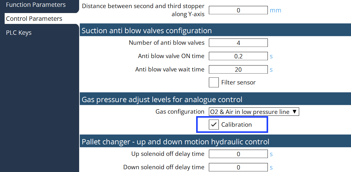
    gas2

  1. Check the values of High Pressure & Low pressure valves.
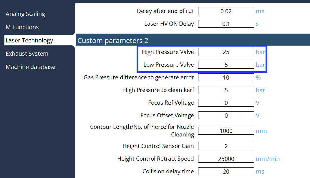
    gas3

  2. Select the Gas Purge program, if the calibration is activated in the PLC options, then the Calibration option will be displayed in this program.
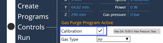
    gas4

  3. When the calibration is selected, the table will be displayed as follow:
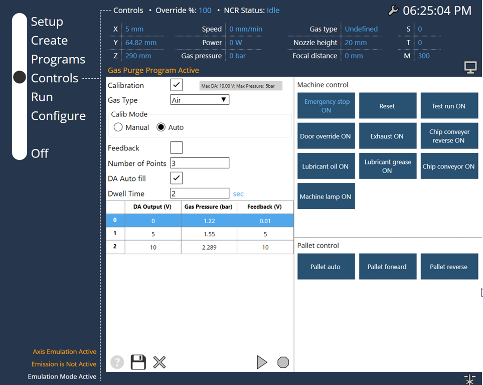
    analog

Important points of the Calibration screen:

  1. The calibration table will be stored for each gas type.

  2. Max pressure value was displayed depends on the Gas configuration and Pressure values entered in "Custom Parameters 2".

  3. Calib Mode : Manual → Press start button for next output, Auto → For defined delay will output the next value

  4. If Feedback is selected, then the Valve feedback is saved for the monitoring of the gas pressure (else will save the set value no monitoring).

  5. DA Auto fill → will fill the DA output depends on the number of calibration points.

  6. When the calibration is started, enter the gas pressure in the pop-up window for each output value.

  7. Can start the calibration from the selected index also.

Frog Jumping Cutting Tools

      Copyright © 2024 by Trumpf-Metamation. All rights reserved.

    Compiled by Bento