Edit layout
Vulcan Control supports the FXLYT format from Flux. The benefit of using FXLYT files is that it is malleable and there will be a lot more that the operator can do with such files than with hardened DIN files.
User needs to select a layout file and then press edit to go to the Edit layout page. It has five options as below:
-
Part
-
Contour
-
Tooling
-
Skeleton
-
Sequence
Part
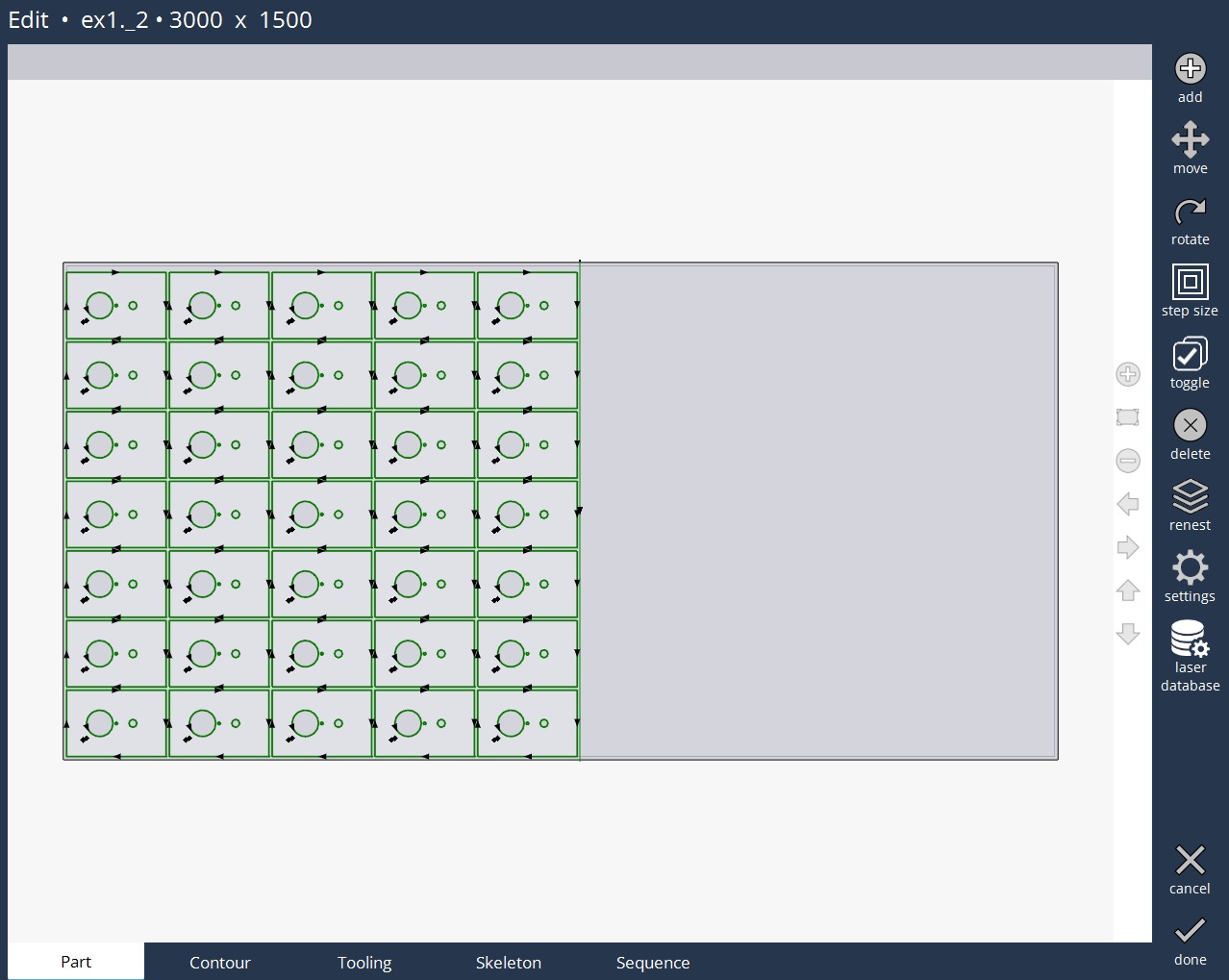
Add : User can add DXF parts in the layout.
Move : The selected part in the layout can be moved using this option.
-
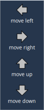
Move left : The part moves to the left.
-
Move right : The part moves to the right.
-
Move up : The part moves to the top.
-
Move down : The part moves to the bottom.
The amount by which the part moves depend on the selected step size.
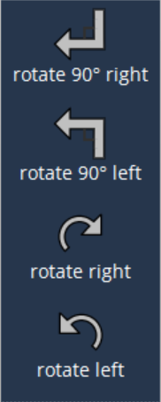
Rotate : The selected part in the layout can be rotated using this option.
-
Rotate 90 degree right : The part rotates 90 degree in clockwise direction.
-
Rotate 90 degree left : The part rotates in 90 degree in anti-clockwise direction.
-
Rotate right : The part rotates in clockwise direction.
-
Rotate left : The part rotates in anti-clockwise direction.
The amount by which the part rotates depends on the selected step size.
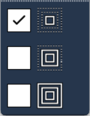
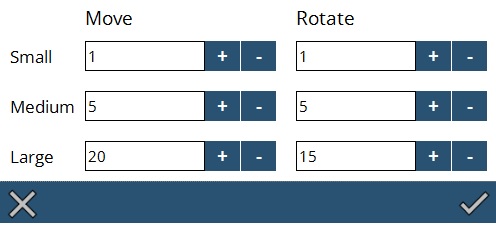
Step size : Based on the value given for Small, Medium and Large for Move and Rotate, part will be moved and rotated correspondingly. User can edit the value based on their preferences.
Toggle : User can select any one part and click toggle option to select all other remaining parts. Selecting multiple parts can be done by clicking the respective parts. Deselecting can be done by clicking on the selected parts. Then they can be moved, rotated or deleted together.
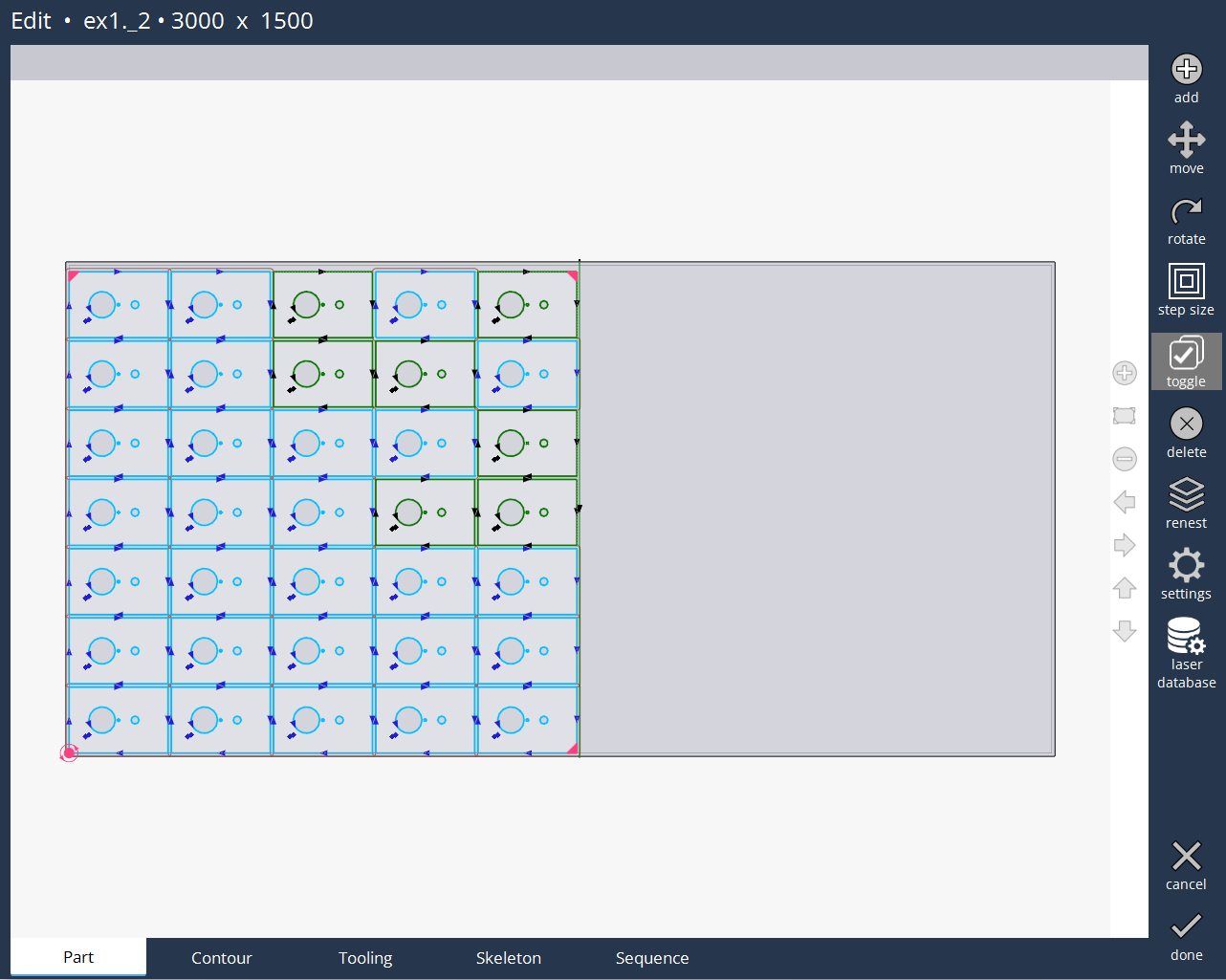
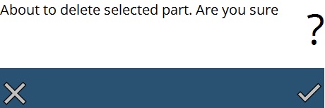
Delete : User can delete the part as per the selection. Click YES in the popup to delete.
Renest : User can use the renest option to nest all the parts in the layout.
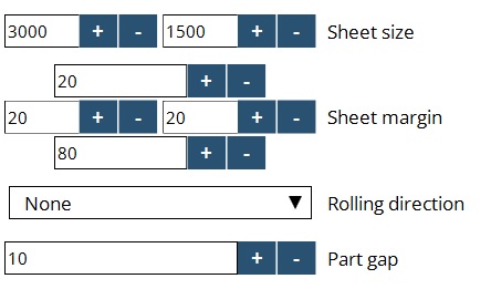
Part settings : User can use this option to change the sheet size, sheet margin, rolling direction and part gap.
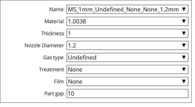
Laser database : User can use this option to change the laser data page which contains material, thickness, nozzle diameter, gas type, treatment and film.
Contour
In this page, user can select the contours and then use these options to edit.
-
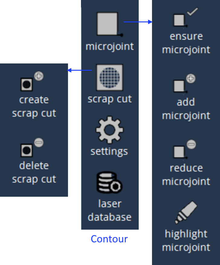
Microjoint : User needs to select the contour before selecting any of the options given below:
-
Ensure Microjoint : If a selected contour already has one or more microjoints, do nothing, otherwise, insert a microjoint.
-
Add Microjoint : This option adds multiple microjoints to the selected contour.
-
Reduce Microjoint : This option reduces the microjoint for the selected contour.
-
Highlight Microjoint : This option highlights the microjoints in the layout.
-
-
Scrap cut : User needs to select the inner contour to perform the below options:
-
Create scrap cut : This option is used to create scrap cut.
-
Delete scrap cut : This option deletes the selected scrap cut.
-
-
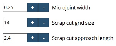
Contour settings : This option is used to change the microjoint width, scrap cut grid size and scrap cut approach length.
Tooling
Using this option, user can move the approach to the targeted point and can edit the tooling parameters by selecting the contour.
-
Move approach : This option is used to move the approach by selecting the approach point and moving to the new targeted point.
-
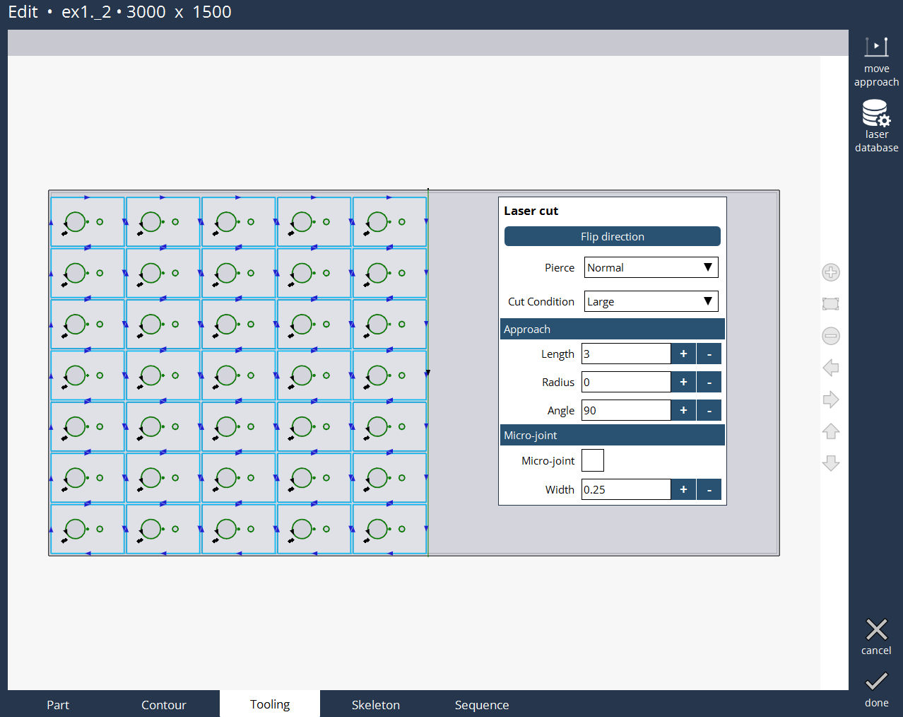
Laser cut : By selecting the tooling, dialog box opens. User can make changes to the laser tooling.
-
User can flip the direction of the cut from clockwise to anti clockwise or vice-versa.
-
Choose the pierce type based on the requirement.
-
Choose the cutting conditions based on the requirement.
-
Change the approach parameters - Length, Radius and Angle based on the requirement.
-
Enable/Disable the Microjoint and change its width based on the requirement.
Skeleton
In this page, user can move and delete slice line once the create sheet cut is enabled from the settings.
-
Move slice line : to create the slice line and then select the slice line to move left or right as per the distance given in the step size.
-
Delete slice line : User needs to select the slice line and then delete it by using delete slice line option.
-
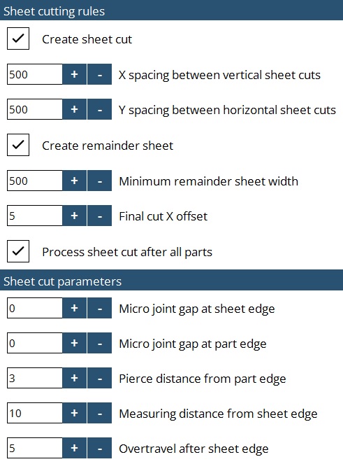
Skeleton settings :
-
Create sheet cut : Whether the sheet skeleton must be sliced or not.
-
X & Y Spacing : This is the spacing between vertical and horizontal slice lines respectively.
-
Create remnant sheet : Enable or disable remainder sheet to create or delete remnant cut respectively.
-
Minimum remnant sheet width : Even if the above is checked, a final cut will be added only when the width of the unused sheet created by the cut is greater than or equal to this value.
-
Final cut X offset : This is the distance from the right most extreme of part tooling to the final vertical cut that creates the remnant sheet.
-
Process slice lines after all parts : Turning it on will cut the parts first then the sheet. The following parameters effect how each individual slice cut is programmed:
-
Microjoint gap at sheet edge : Set this to a value greater than zero if you want a small web left at the points where the slice cut touches the sheet edge.
-
Microjoint gap at part edge : Set this to a value greater than zero if you want a small web left at the points where the slice cut touches the part edge.
-
Pierce distance from part edge : This is the distance of the pierce point from the part edge.
-
Measure distance from sheet edge : This parameter identifies the distance before the sheet edge where the laser head height is locked, and distance regulation is turned off.
-
Overtravel after sheet edge : This is the amount by which the machine head travels beyond the sheet edge with laser on but distance regulation off.
Sequence
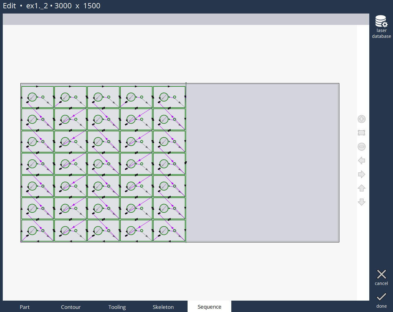
It shows the cut sequence of the layout.
Cancel : All the changes that were made will be lost. It will go back to programs page.
Save : It saves all the changes.