
Vulcan Reference Manual

  • Welcome to Vulcan Control
  • Introduction
    • User interface
    • Workflow
    • Machine Operation
    • Control panel
  • Production Workflow
    • Preparation
    • Create
    • File Management
    • Select Program
    • Edit NC Code
    • Edit Laser Technology
    • Edit layout
    • Simulation run
    • Work offsets
    • Run
    • Re-entry
  • Laser Technology Tables (LTT)
    • Terminology
    • Laser Data items
      • Piercing
      • Multistage Piercing
      • Cutting
      • Special Processes
    • Modifying Laser Data
    • LTT Management
    • Ramp Cycles
    • FlyLine
    • Acceleration control (DCA)
  • Technology functions
    • Vaporize Sheet
    • Nanojoints
    • PierceLine Sensor
    • Frog Jumping
    • Cutting Tools
  • Controls
    • Lubrication Cycle
    • Protective Glass Monitoring
    • Scrap Cut
    • Go To Sheet Origin
    • Height Sensor Calibration
    • Nozzle Centre
    • Target Shot
    • Gas Purge
    • HC Manual Set Point
    • Go To Park Position
    • Nozzle Clean & Height Sensor Calibration
    • Edge Detection
    • Focus Comb
    • Focal Distance
    • Pilot Diode Positioning
  • Production plan
    • Create a production plan
    • Modification
    • Run a production plan
    • Running sequence
    • sheet loading
    • Material stock
  • Drop and Cut
  • Troubleshooting
    • Frequent collisions
    • Work offset
    • Extreme small contours
  • NC Programming Reference
    • DIN format
      • DIN Program Structure
        • Program Number %
        • Block number N
        • G-functions
        • M-functions
        • Parameter Array
        • Graphical Element – Display Marker Lines
      • Laser Technology
        • Program Header
        • Technology Table (TT) Transfer
        • Check for Bound Program Active
        • Block Jump
        • Block Number
        • Start of a Part information
        • Laser parameters selection & Update
        • Contour Statements
        • Program End (G99)
        • Remnant Cut
          • Start Remnant Cut
          • End Remnant Cut
        • FlyLine
        • Only Piercing in the Contour
        • Nano Joints
        • Sample Program with Multiple Parts
        • Fly Cut Sample Program:
    • LST format
      • LST Program Structure
      • FlyLine
      • TC_WRITE
      • Incremental Command (IC)
      • Soft Micro-Joints & Nano-Joints
    • Laser Technology commands
      • Laser cutting
      • Identifying parts
      • Multiple program structure
      • Cutting distance
      • Kerf correction
      • Overshoot height
      • Timing of parts
      • Bevel cut
      • Beam suppression
      • Flying focus position alteration
  • Impressum
NC Programming Reference
/
DIN format
/
DIN Program Structure
/
Graphical Element – Display Marker Lines

Graphical Element – Display Marker Lines

It is possible to display dashed marker lines in the HMI in the DIN program display. Insert the respective graphical marks before and after the contour which is to be shown dashed and applicable only for STDHMI.

    {LB,K0} (Start Line display)
    G1 X124.5 Y35.5
    G3 X115.5 Y35.5 I-4.5 J0
    G1 X115.5 Y24.5
    G3 X124.5 Y24.5 I4.5 J0
    G1 X124.5 Y30
    {LE} (End Line display)
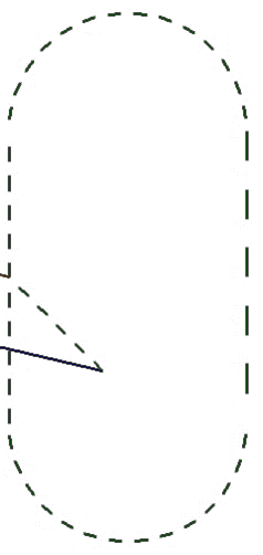
image2

In the DIN program display, the contour which is to be marked is showed in dashed lines for better understanding of the operator.

Parameter Array Laser Technology

      Copyright © 2025 TRUMPF Metamation. All rights reserved.

    Compiled by Bento