Beam suppression
TC_MICROJOINT
Microjoints are microwebs that could usually be programmed only with the programming system TruTops. The microjoints defined in this way are permanently anchored in the NC program. They cannot be modified or deselected during the machining of parts at the machine.
Nanojoints specifically create small connections on the underside of the sheet between the cut part and the scrap skeleton. Nanojoint is only available for certain cutting processes and sheet thicknesses (see "Cutting data" in the data collection tables).
Depending on the machine, it may also be possible to program microjoints/nanojoints directly on the machine and select or deselect them as required. There are two different types of microjoints:
-
Programmed microjoints/nanojoints that are defined within the contour or at the end of the contour via G functions. The contour is marked here directly in the NC text for the part program.
-
Automatic microjoints/nanojoints that are always set at the end of the contour and defined without G functions. The definition is made here via the dimension of the contour in X- and Y-direction. The contour is not marked in the NC text.
The following points are valid:
-
Microjoints that can only be modified at the machine are only possible on the machine on surfaces of rectangular tubes or for plane processing.
-
The data for programmed microjoints is stored in a programspecific table. The data can be displayed and modified via the user interface of the control. This table can be used to activate and deactivate the microjoint types separately. The table is called up using the NC cycle TC_MICROJOINT ("table name").
-
The activation status of the microjoints in the table is stored with the program. In this way, an available program is guaranteed to be processed under the same conditions after every program change, even when fully automatic systems are used.
Call up table with microjoint data directly at the control system and activate or deactivate programmed- or automatic microjoints in the NC text.
The cycle TC_MICROJOINT in the NC program calls up the table containing all the parameters and the activation status of the functions. Data can be modified in the table. The modified table is updated automatically in the NC core.
TC_MICROJOINT("Table name"):
-
Self-holding (modal) operation.
-
Call up as early as possible before the required contour machining.
-
Is deselected using program end or with the selection of a new table.
| ID | Parameter | Values | Unit | Description |
|---|---|---|---|---|
10 |
Table identifier |
- |
- |
Name of the table, e.g. "MIJO-1" |
100 |
Programmed MicroJoints active |
0 |
- |
Programmed MicroJoints not active |
1 |
- |
Programmed MicroJoints active |
||
110 |
Automatic Microjoints active |
0 |
- |
Automatic Microjoints not active |
1 |
- |
Automatic Microjoints active |
||
120 |
Large MicroJoint small contour |
mm |
Microjoint size small contour |
|
130 |
Large MicroJoint medium contour |
mm |
Microjoint size medium contour |
|
140 |
Large MicroJoint large contour |
mm |
Microjoint size large contour |
|
150 |
Min. contour dimension in X |
mm |
Min. contour dimension in X |
|
160 |
Max. contour dimension in X |
mm |
Max. contour dimension in X |
|
170 |
Min. contour dimension in Y |
mm |
Min. contour dimension in Y |
|
180 |
Max. contour dimension in Y |
mm |
Max. contour dimension in Y |
|
190 |
Piercing type after Microjoints (PiercingTypeAfterMicrojoint) |
Piercing type after Microjoints |
||
10 |
- |
Normal piercing |
||
11 |
- |
Gentle piercing |
||
270 |
Automatic nanojoints active (AutomaticNanoJointActive) |
0 |
- |
Automatic nanojoints not active |
1 |
- |
Automatic nanojoints active |
||
280 |
Programmed nanojoints active (NanoJointProgramActive) |
0 |
- |
Programmed nanojoints not active |
1 |
- |
Programmed nanojoints active |
||
290 |
Stability of the nanojoints (NanoJointStabilityLargeContour) |
- |
- |
Stability of large contour nanojoints. |
0 |
- |
Normal. |
||
1 |
- |
Increased. |
||
-1 |
- |
Reduced. |
G821
Defining programmable, contour related microjoints.
With this G function, the NC block within the contour is marked by setting a microjoint. The microjoint can be set within the contour or at the end of the contour.
If the microjoint is set within the contour, then piercing is automatically renewed.
Restrictions for microjoints within the contour:
-
Special forms of piercing, such as the "back-step", for example, are not supported. This is due to the approach procedure not being possible afterwards in the contour.
-
Approaching with reduced cutting parameters and subsequent switching to normal parameters is not possible.
| Depending on the machine, special shapes are possible via the TC_LEAD_IN cycle (see "TC_LEAD_IN", pg. 5‐34). |
G821:
| The G821 function is assigned to a group of G commands. Only one G command may be used from this group within an NC block. The G commands belong to this group G820 – G829. |
-
Is considered if programmed microjoints are activated or deactivated via the microjoint table.
-
Is not activated in the microjoint table as default. Standard: 0 = not activated; 1 = activated.
-
Is written into the contour’s NC block, at the end of which the microjoint is to be set.
-
Is immediately effective after activation if the laser cutting head within the positioning motion is located between two contours. If the laser cutting head is, however, found directly at the machining of a contour, then the function only becomes effective for the next contour machining.
-
Should the function be deactivated when a contour is being machined, then another microjoint will be set in this contour. The following contour is machined without a microjoint. If the machining head is found between two contours within a positioning motion, then the following contour will be machined without a microjoint.
Programmed microjoints at the end of the contour:
| Block | NC program | Description |
|---|---|---|
N70 |
TC_MICROJOINT ("MJT1") |
- |
… |
… |
- |
N200 |
TC_LASER_ON(1,"4711",10,100) |
Laser on |
N210 |
G02 X20 Y60 J-10 G821 |
Full circle with microjoint at the end of the contour |
N220 |
TC_LASER_OFF(1) |
Laser OFF |
… |
… |
- |
N400 |
TC_LASER_ON(1,"4711",10,100) |
Laser on |
N410 |
G02 X40 Y10 J-10 |
Oblong |
N420 |
G01 X20 Y10 |
- |
N430 |
G02 X20 Y30 J10 G821 |
Oblong hole with microjoint at the end of the contour |
N440 |
TC_LASER_OFF(1) |
Laser OFF |
Programmed microjoints in the contour:
| Block | NC program | Description |
|---|---|---|
… |
… |
- |
N110 |
TC_LEAD_IN("LIT-1", T_LEFT) |
- |
N200 |
TC_LASER_ON(1,"4711",10,100) |
Laser on |
N210 |
G02 X20 Y40 J-10 G821 |
1. Semicircle of full circle with microjoint within the contour |
N220 |
G02 X20 Y60 J10 |
2. Semicircle of full circle without microjoint |
N230 |
TC_LASER_OFF(1) |
Laser OFF |
… |
… |
- |
N400 |
TC_LASER_ON(1,"4711",10,100) |
Laser on |
N410 |
G01 X40 Y30 |
Oblong |
N420 |
G02 X40 Y10 J-10 G821 |
1. Part of the oblong hole with microjoint within the contour |
N430 |
G01 X20 Y10 J10 G821 |
- |
N430 |
G02 X20 Y30 J10 |
- |
N450 |
TC_LASER_OFF(1) |
Laser OFF |
G822
Skipping automatic microjoint in relation to the contour.
The criteria for an automatically set microjoint at the end of a contour is the dimension of the contour in X- and Y-direction. If the maximum dimension of the contour in X- or Y-direction lies within a range also defined in the microjoint table, then a microjoint is automatically set at the end of every contour.
Because the control system cannot differentiate between closed and open contours, every open contour must already be marked as such in the programming system. Otherwise, microjoints will also be set at open contours, i.e. these open contours will be shortened.
With G function G822, unwanted, automatic microjoints can now be skipped on the control.
G822:
| The G822 function is allocated to a group of G commands. Only one G command may be used from this group within an NC block. The G commands belong to this group G820 – G829. |
-
Is considered if automatic microjoints are activated or deactivated via the microjoint table. The table is called via TC_MICROJOINT ("table name").
-
Is not activated in the microjoint table as default. Standard: 0 = not activated; 1 = activated.
-
Can be written for the respective contour in a separate block or at the end of an NC block, but after TC_LASER_ON and before TC_LASER_OFF.
-
Is immediately effective after activation if the laser cutting head within the positioning motion is located between two contours. If the laser cutting head is, however, found directly at the machining of a contour, then the function only becomes effective for the next contour machining.
-
Should the function be deactivated when a contour is being machined, then another microjoint will be set in this contour. The following contour is machined without a microjoint. If the machining head is found between two contours within a positioning motion, then the following contour will be machined without a microjoint.
-
Is cleared with the next TC_LASER_OFF.
| Block | NC program | Description |
|---|---|---|
N200 |
TC_LASER_ON(1,"4711",10,100) |
Laser on |
N205 |
G822 |
Skipping automatic microjoint Separate NC block |
N210 |
G02 X20 Y60 J-10 G821 |
Full circle with microjoint at the end of the contour |
N220 |
TC_LASER_OFF(1) |
Laser OFF |
… |
… |
- |
N400 |
TC_LASER_ON(1,"4711",10,100) |
Laser on |
N410 |
G02 X40 Y10 J-10 G822 |
Oblong hole with suppression of an automatic microjoint At the end of the NC block |
N420 |
G01 X20 Y10 |
- |
N430 |
G02 X20 Y30 J10 G821 |
Oblong hole with microjoint at the end of the contour |
N440 |
TC_LASER_OFF(1) |
Laser OFF |
G824
Set programmable nanojoints.
Nanojoints hold the part only at the lower cutting area. This is achieved by reducing the laser power for a short time. Nanojoints are suitable for sophisticated parts, or if it should be possible to break parts out of the remainder sheet easily.
G824:
| The G824 function is allocated to a group of G commands. Only one G command may be used from this group within an NC block. The G commands belong to this group G820 – G829. |
-
It is taken into account if programmable nanojoints are activated or deactivated via the nanojoint table. The table is called via TC_MICROJOINT ("table name").
-
It is not activated in the nanojoint table by default. Standard: 0 = not activated; 1 = activated.
-
Can be written for the respective contour in a separate block or at the end of an NC block, but after TC_LASER_ON and before TC_LASER_OFF.
-
Is immediately effective after activation if the laser cutting head within the positioning motion is located between two contours. If the laser cutting head is, however, found directly at the machining of a contour, then the function only becomes effective for the next contour machining.
-
Should the function be deactivated when a contour is being processed, another nanojoint will be set in this contour. The following contour is processed without nanojoint. If the processing head is within a positioning motion between two contours, then the following contour will be processed without a nanojoint.
-
Is cleared with the next TC_LASER_OFF.
| Block | NC program | Description |
|---|---|---|
N100 |
G90 X20 Y60 F100000 |
- |
N200 |
TC_LASER_ON(1,"HUGO",10,100) |
Laser on |
N210 |
G2 X20 Y60 J-10 G824; full circle |
Full circle with nanojoint at the end of the contour |
N220 |
TC_LASER_OFF(1) |
Laser OFF |
… |
… |
- |
N400 |
TC_LASER_ON(1,"HUGO",10,100) |
Laser on |
N410 |
G02 X40 Y10 J-10; oblong hole |
Oblong hole with suppression of an automatic nanojoint |
N420 |
G01 X20 Y10 |
- |
N430 |
G02 X20 Y30 J10 G824 |
Oblong hole with nanojoint at the end of the contour |
N440 |
TC_LASER_OFF(1) |
Laser OFF |
N500 |
G1 X0 Y0 |
- |
TC_LEAD_IN
With the TC_LEAD_IN cycle call-up in the NC program, technology parameters for the optimum approach strategy are selected after a microjoint.
The cycle is possible in the following machines:
-
TruLaser 1000 series
-
TruLaser Series 3000
-
TruLaser Series 5000
TC_LEAD_IN("Approach table", approach direction):
-
Approach table:
-
The tables contain all relevant information about parameters and methods of the approach procedure.
-
-
Approach direction:
-
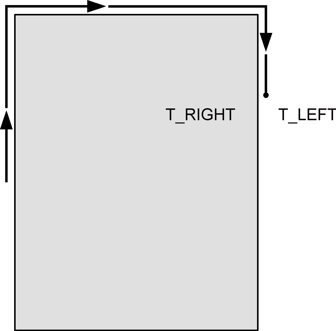
Depending on the parameter setting, the programmed contour is approached to the left or right of the direction of machining.
-
TC_LEAD_IN ("Approach table", T_LEFT): Approaching the programmed contour on the left of the direction of movement.
-
TC_LEAD_IN ("Approach table", T_RIGHT): Approaching the programmed contour on the right of the direction of movement.
-
| The parameter Approach direction marks the range for the finished part and scrap of a part. |
| ID | Parameter | Values | Unit | Description |
|---|---|---|---|---|
10 |
Table identifier |
- |
- |
Name of the table, e.g. "LI-1" |
20 |
Small contour approach strategy |
1 |
- |
Full approach without precut. |
2 |
- |
Reduced approach on the first 80% of the linear approach path without precut. |
||
3 |
- |
Approach with precut, reduced approach until the piercing point is reached again. |
||
30 |
Medium contour approach strategy |
1-3 |
- |
For value range and description, see ID20. |
40 |
Large contour approach strategy |
1-3 |
- |
For value range and description, see ID20. |
50 |
Small contour piercing type (PiercingTypeSmall) |
10 |
- |
Normal piercing. |
11 |
- |
Gentle piercing. |
||
60 |
Medium contour piercing type (PiercingTypeMedium) |
10-11 |
- |
For value range and description, see ID50. |
70 |
Large contour piercing type (PiercingTypeLarge) |
10-11 |
- |
For value range and description, see ID50. |
80 |
Small contour approach method |
1 |
- |
Piercing and cutting with distance regulation. |
2 |
- |
Piercing and cutting without distance regulation. |
||
3 |
- |
Piercing without distance regulation, cutting with distance regulation. |
||
4 |
- |
Piercing with distance regulation, cutting without distance regulation. |
||
5 |
- |
No piercing, cut with distance regulation. |
||
9 |
- |
Piercing without ramp cycle, cut with distance regulation with analog laser power control (SprintLine). |
||
10 |
- |
Piercing without ramp cycle, cut without distance regulation with analog laser power control (SprintLine). |
||
11 |
- |
No piercing, cut with distance regulation with analog laser power control (SprintLine). |
||
90 |
Medium contour approach method |
1-11 |
- |
For value range and description, see ID80. |
100 |
Large contour approach method |
1-11 |
- |
For value range and description, see ID80. |
110 |
Small contour approach cutting type |
The coding contains three digits:
|
||
0 |
- |
No cutting. |
||
300 |
- |
Cutting small contour, normal acceleration. |
||
310 |
- |
Cutting small contour, reduced approach from the piercing hole, normal acceleration. |
||
330 |
- |
Cutting small contour, reduced approach in the thick sheet, normal acceleration. |
||
120 |
Medium contour approach cutting type |
0 |
- |
No cutting. |
200 |
- |
Cutting medium contour, normal acceleration. |
||
210 |
- |
Cutting medium contour, reduced approach from the piercing hole, normal acceleration. |
||
230 |
- |
Cutting medium contour, reduced approach in the thick sheet, normal acceleration. |
||
130 |
Large contour approach cutting type |
0 |
- |
No cutting. |
100 |
- |
Cutting large contour, normal acceleration. |
||
110 |
- |
Cutting large contour, reduced approach from the piercing hole, normal acceleration. |
||
130 |
- |
Cutting large contour, reduced approach in the thick sheet, normal acceleration |
||
140, 150, 160 |
Vaporizing Type |
Vaporizing type
|
||
140 |
Small contour vaporizing type |
0 |
- |
No vaporizing. |
1 |
- |
Circular vaporizing only at the piercing hole. |
||
2 |
- |
Vaporizing of the entire approach flag. |
||
150 |
Medium contour vaporizing type |
0-2 |
- |
For value range and description, see ID140. |
160 |
Large contour vaporizing type |
0-2 |
- |
For value range and description, see ID140. |
170 |
Small contour length of straight lines |
mm |
Length of the linear part of the approach flag. |
|
180 |
Medium contour length of straight lines |
mm |
Length of the linear part of the approach flag. |
|
190 |
Large contour straight line length |
mm |
Length of the linear part of the approach flag. |
|
200 |
Small contour arc radius |
mm |
Radius of the transition curve between the linear part of the approach flag and the entry point in the contour. |
|
210 |
Medium contour arc radius |
mm |
Radius of the transition curve between the linear part of the approach flag and the entry point in the contour. |
|
220 |
Large contour arc radius |
mm |
Radius of the transition curve between the linear part of the approach flag and the entry point in the contour. |
|
230 |
Small contour approach angle |
° |
Angle between linear part of the approach flag and tool path (corresponds to the angle of the arc). |
|
240 |
Medium contour approach angle |
° |
Angle between linear part of the approach flag and tool path (corresponds to the angle of the arc). |
|
250 |
Large contour approach angle |
° |
Angle between linear part of the approach flag and tool path (corresponds to the angle of the arc). |
|
260 |
Small contour precut length |
mm |
Length of the path that is precut during approach strategy 3 on the linear part of the approach flag cut in reduced mode. The precut length is limited to the value of the parameter "Straight line length". |
|
270 |
Medium contour precut length |
mm |
Length of the path that is precut during approach strategy 3 on the linear part of the approach flag cut in reduced mode. The precut length is limited to the value of the parameter "Straight line length". |
|
280 |
Large contour precut length |
mm |
Length of the path that is precut during approach strategy 3 on the linear part of the approach flag cut in reduced mode. The precut length is limited to the value of the parameter "Straight line length". |