Vulcan Reference Manual

  • Welcome to Vulcan Control
  • Introduction
    • User interface
    • Workflow
    • Machine Operation
    • Control panel
  • Production Workflow
    • Preparation
    • Create
    • File Management
    • Select Program
    • Edit NC Code
    • Edit Laser Technology
    • Edit layout
    • Simulation run
    • Work offsets
    • Run
    • Re-entry
  • Laser Technology Tables (LTT)
    • Terminology
    • Laser Data items
      • Piercing
      • Multistage Piercing
      • Cutting
      • Special Processes
    • Modifying Laser Data
    • LTT Management
    • Ramp Cycles
    • FlyLine
    • Acceleration control (DCA)
  • Technology functions
    • Vaporize Sheet
    • Nanojoints
    • PierceLine Sensor
    • Frog Jumping
    • Cutting Tools
  • Controls
    • Lubrication Cycle
    • Protective Glass Monitoring
    • Scrap Cut
    • Go To Sheet Origin
    • Height Sensor Calibration
    • Nozzle Centre
    • Target Shot
    • Gas Purge
    • HC Manual Set Point
    • Go To Park Position
    • Nozzle Clean & Height Sensor Calibration
    • Edge Detection
    • Focus Comb
    • Focal Distance
    • Pilot Diode Positioning
  • Production plan
    • Create a production plan
    • Modification
    • Run a production plan
    • Running sequence
    • sheet loading
    • Material stock
  • Drop and Cut
  • Troubleshooting
    • Frequent collisions
    • Work offset
    • Extreme small contours
  • NC Programming Reference
    • DIN format
      • DIN Program Structure
        • Program Number %
        • Block number N
        • G-functions
        • M-functions
        • Parameter Array
        • Graphical Element – Display Marker Lines
      • Laser Technology
        • Program Header
        • Technology Table (TT) Transfer
        • Check for Bound Program Active
        • Block Jump
        • Block Number
        • Start of a Part information
        • Laser parameters selection & Update
        • Contour Statements
        • Program End (G99)
        • Remnant Cut
          • Start Remnant Cut
          • End Remnant Cut
        • FlyLine
        • Only Piercing in the Contour
        • Nano Joints
        • Sample Program with Multiple Parts
        • Fly Cut Sample Program:
    • LST format
      • LST Program Structure
      • FlyLine
      • TC_WRITE
      • Incremental Command (IC)
      • Soft Micro-Joints & Nano-Joints
    • Laser Technology commands
      • Laser cutting
      • Identifying parts
      • Multiple program structure
      • Cutting distance
      • Kerf correction
      • Overshoot height
      • Timing of parts
      • Bevel cut
      • Beam suppression
      • Flying focus position alteration
  • Impressum
Introduction
/
Control panel

Control panel

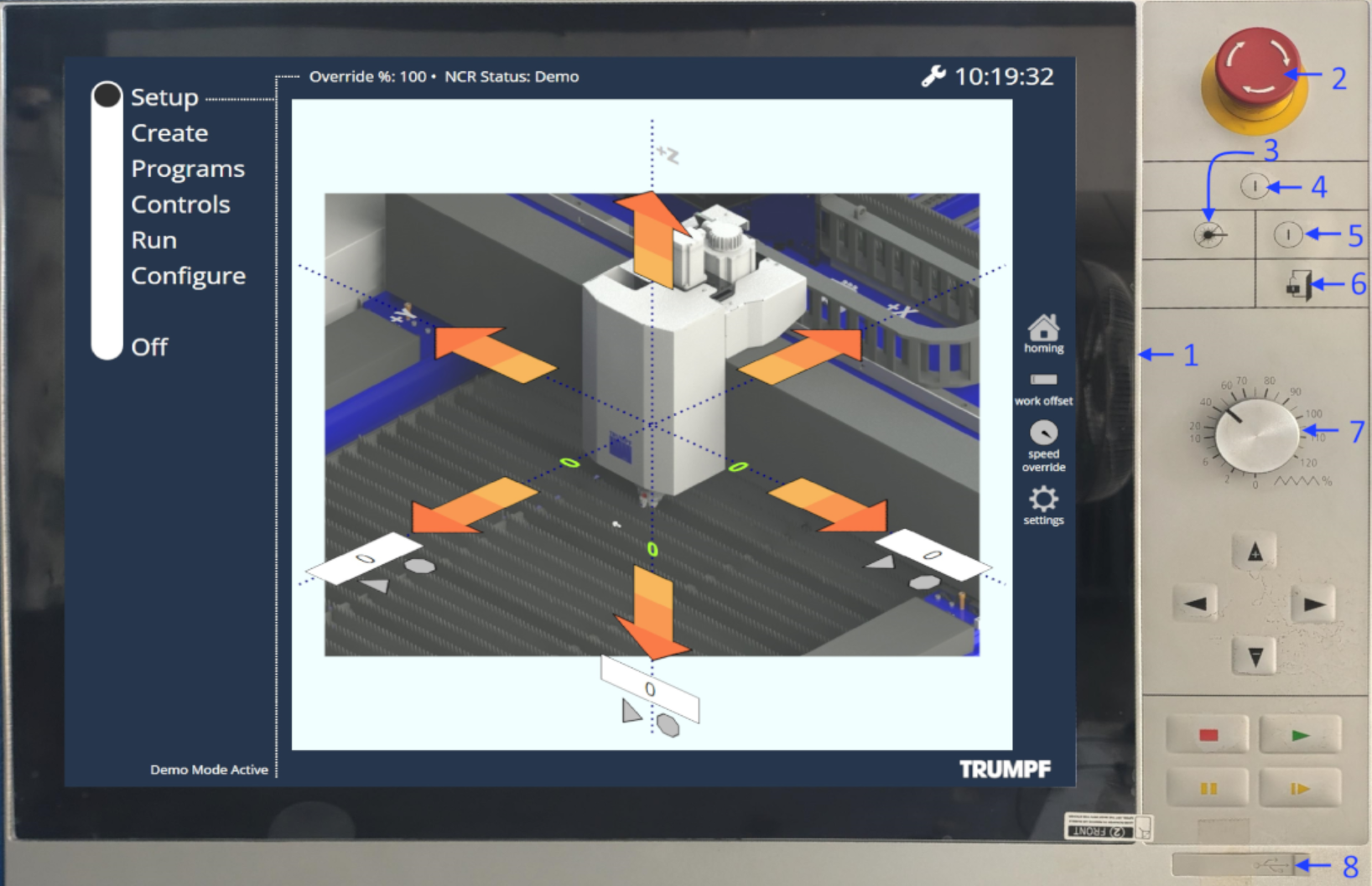
The Control panel is an essential component to prepare the laser machine for operation. Please refer to the operation manual for more details.

import1

The Control panel consists of the following control switches:

  1. Display

  2. Emergency stop

  3. Laser test mode

  4. Drive enable key

  5. Laser enable

  6. Door switch

  7. Override

  8. USB port

Name Operating element Requirements Description

EMERGENCY STOP (push button)

w1

  • The power supply to the entire system is disconnected (the 24 V control voltage is maintained).

    • All axis motions stop.

    • All drives are switched off electrically.

  • The processing is interrupted:

    • The laser beam is switched off.

    • The beam block is closed.

    • The gas supply of the cutting gas is interrupted.

    • An active processing program is aborted and needs to be restarted, if required.

    • The machine’s home position has to be approached.

    • The reference points of the axes are retained.

  • The hydraulic unit, the compact dust extractor and the length wise and/or transverse conveyor, respectively, are switched off.

  • All pneumatic movements are stopped or transferred to a dan ger-free state. The compressed air supply remains unaffected.

  • Vacuum remains.

Machine On/Off

w2

Switching on, The button flashes.

  • Switches the machine On:

    • Lights up when the machine is ready for operation.

  • Switches the machine Off:

    • Goes out when machine switched off.

  • Machine Off is also triggered by:

    • "EMERGENCY STOP" push-button.

    • Errors which trigger an "EMERGENCY STOP"

Laser test

w3

  • Is lit if the machine is in test mode.

  • The selected processing program will run without the laser beam being ignited.

Laser On/Off

w4

  • Starts the automatic switch-on cycle of the laser:

    • Flashes while the switch-on cycle is being carried out.

    • Is lit if the laser is ready for operation.

  • Starts the automatic switch-off cycle of the laser:

    • Flashes while the switch-off cycle is being carried out.

    • Goes out when machine switched off.

Door unlocking

w5

Safety door is unlocked and can be opened.

Status display (Safety light barrier interrupted)

w6

"EMERGENCY STOP" is not active, No "Feed hold" is active.

  • Flashes when the safety light barrier which shields the pallet changer is interrupted.

  • Reactivate safety light barrier: Press "Acknowledge safety light barrier" foot switch on the start post. Then press "Start" button on the control panel. Continue the paused movements of the pallet changer: press "Start"

Feed rate

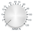
w7

  • Controls the travel speed of the X and Y axes between 4 and 120%:

  • In the Production core operation, the travel regulation is 4-100 m/min.

Navigation keys

w8

  • Moves the selected NC axes in the (+) or (-) direction.

    • Moves the axes in the +/- direction.

    • The plus/minus buttons increase/reduce the value of "Manual functions" with the symbol ±.

Reset (Stop)

w9

  • Deletes active fault messages.

  • Cancels an active program.

  • The reference points are maintained.

  • The home position might be lost.

Feed hold (Pause)

w10

  • Lights up if "FEED HOLD" is triggered.

    • All axis motions stop.

    • The processing is interrupted:

      • The laser beam is switched off.

      • The beam block is closed.

      • The gas supply of the cutting gas is interrupted.

      • An active processing program is paused and can be further executed by acknowledging.

  • The hydraulic unit, the compact dust extractor and the length wise and/or transverse conveyor, respectively, are switched off.

  • All pneumatic movements are stopped or transferred to a dan ger-free state. The compressed air supply remains unaffected.

  • Vacuum remains, To acknowledge any "feed hold", press "Acknowledge feed hold".

Acknowledging feed stop (Feed start)

w11

No errors present, The safety light barrier is acknowledged.

  • Flashes if an error is present or a "FEED HOLD" has been triggered

  • For example, by interrupting the safety light barrier, Acknowledges active error, Acknowledge "FEED HOLD".

Start (Program start)

w12

No errors present, Machine is ready to operate.

  • The "Start" button has the following functions depending on the core operation selected:

    • If the Setup core operation is selected: the machine moves to the home position without starting to execute the order list or the selected processing program.

    • In all other core operations: the machine moves to the home position and starts executing the order list.

Machine Operation Production Workflow

      Copyright © 2025 TRUMPF Metamation. All rights reserved.

    Compiled by Bento