
Vulcan Reference Manual

  • Welcome to Vulcan Control
  • Introduction
    • User interface
    • Workflow
    • Machine Operation
    • Control panel
  • Production Workflow
    • Preparation
    • Create
    • File Management
    • Select Program
    • Edit NC Code
    • Edit Laser Technology
    • Edit layout
    • Simulation run
    • Work offsets
    • Run
    • Re-entry
  • Laser Technology Tables (LTT)
    • Terminology
    • Laser Data items
      • Piercing
      • Multistage Piercing
      • Cutting
      • Special Processes
    • Modifying Laser Data
    • LTT Management
    • Ramp Cycles
    • FlyLine
    • Acceleration control (DCA)
  • Technology functions
    • Vaporize Sheet
    • Nanojoints
    • PierceLine Sensor
    • Frog Jumping
    • Cutting Tools
  • Controls
    • Lubrication Cycle
    • Protective Glass Monitoring
    • Scrap Cut
    • Go To Sheet Origin
    • Height Sensor Calibration
    • Nozzle Centre
    • Target Shot
    • Gas Purge
    • HC Manual Set Point
    • Go To Park Position
    • Nozzle Clean & Height Sensor Calibration
    • Edge Detection
    • Focus Comb
    • Focal Distance
    • Pilot Diode Positioning
  • Production plan
    • Create a production plan
    • Modification
    • Run a production plan
    • Running sequence
    • sheet loading
    • Material stock
  • Drop and Cut
  • Troubleshooting
    • Frequent collisions
    • Work offset
    • Extreme small contours
  • NC Programming Reference
    • DIN format
      • DIN Program Structure
        • Program Number %
        • Block number N
        • G-functions
        • M-functions
        • Parameter Array
        • Graphical Element – Display Marker Lines
      • Laser Technology
        • Program Header
        • Technology Table (TT) Transfer
        • Check for Bound Program Active
        • Block Jump
        • Block Number
        • Start of a Part information
        • Laser parameters selection & Update
        • Contour Statements
        • Program End (G99)
        • Remnant Cut
          • Start Remnant Cut
          • End Remnant Cut
        • FlyLine
        • Only Piercing in the Contour
        • Nano Joints
        • Sample Program with Multiple Parts
        • Fly Cut Sample Program:
    • LST format
      • LST Program Structure
      • FlyLine
      • TC_WRITE
      • Incremental Command (IC)
      • Soft Micro-Joints & Nano-Joints
    • Laser Technology commands
      • Laser cutting
      • Identifying parts
      • Multiple program structure
      • Cutting distance
      • Kerf correction
      • Overshoot height
      • Timing of parts
      • Bevel cut
      • Beam suppression
      • Flying focus position alteration
  • Impressum
Controls

Controls

This page displays the state of the PLC keys. When the user clicks a PLC key, the UI will be updated based on the acknowledgement from PLC. The PLC keys are assigned fixed text numbers. Numbers 2800-2899 and 2900-2999 are reserved for this purpose.

Example Key assignments to text numbers :

Key0 (first button) 2800,2900
Key1 (second button) 2801,2901

If both texts are present in the text file, the key is available as a switch. If only the first text number is present in the text file (e.g. 2801, but not 2901), the key is available as a button. In data block 1 in the PLC, the HMI signals whether a button or switch was pressed.

The following rules apply :

  • For a button (only one text is defined, the second text is missing), the status is displayed as pressed (1) and not (0).

  • For a switch (both texts are defined), the status is not displayed as pressed and not pressed. Instead, the relevant bit is toggled accordingly each time you press and release the switch.
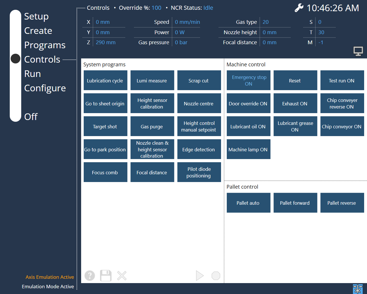
    Controls page
Cutting Tools Lubrication Cycle

      Copyright © 2025 TRUMPF Metamation. All rights reserved.

    Compiled by Bento