
Identifying parts
TC_WRITE
Variable text can be engraved on the workpiece with the TC_WRITE cycle.
The TC_WRITE cycle outputs the text at the current position in positive X direction. The laser technology table, the font height in mm and the text direction in degrees can be changed via the cycle’s corresponding transfer parameter.
| Plane processing should be selected for round tubes. |
TC_WRITE(T_TEXT,T_TABNAME,T_HEIGHT,T_ANGLE)
-
TC_WRITE must be programmed before contour machining (TC_LASER_ON).
| Parameter | Value | Definition |
|---|---|---|
T_TEXT |
- |
Text to be engraved on the workpiece (max. 255 characters). |
T_TABNAME |
- |
Name of the laser technology table. |
T_HEIGHT |
- |
Font size in mm or inch. |
T_ANGLE |
Default value: 0° |
Optional parameter for text rotation in degrees. |
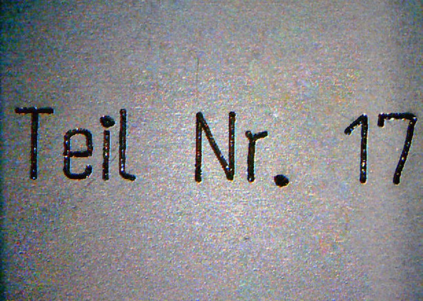
TC_WRITE("Teil Nr. 17","TTBC-8252O2",5,0)
int actNumber = 13
TC_WRITE("Part No.: ”<< actNumber,"TTBC-8252O2",10,0)
The following macros are stored at the machine. They allow production information to be output (date and/or time of the production of a workpiece):
| Macro | Example | |
|---|---|---|
Engrave name of the current main program with program suffix *MPF. |
TM_MAINPROG |
TC_WRITE(TM_MAINPROG,"TTBC-8252O2",10,0) |
Engrave name of the current main program. |
TM_MAINPROG_SHORT |
TC_WRITE(TM_MAINPROG_SHORT,"TTBC-8252O2",10,0) |
Engrave current time. Format: hh:mm:ss. |
TM_TIME |
TC_WRITE(TM_TIME,"TTBC-8252O2",10,0) |
Engrave current date. Metric format: dd.mm.yyyy / Inch format: mm/dd/yyyy |
TM_DATE |
Metric programming: |
Engrave time and current date (formatting depends on the unit of measurement). |
TM_TIMEDATE |
Metric programming: |
Engrave the name of the machine. |
TM_MACHINE_NUMBER |
TC_WRITE(TM_MACHINE_NUMBER,"TTBC-8252O2",0.197,0) |
TC_LABEL
| This function is available for 2D laser machines of the TruLaser Series 5000 and TruLaser Series 3000 with the SINUMERIK ONE control. |
The TC_LABEL cycle can be used to identify workpieces with the following labels: * Data Matrix Code. * Plain text.
TC_LABEL
-
LabelGroup ID: Parameter ID 10 (consecutive number of the part) from the PARTS_IN_PROGRAM_POS table.
-
TC_LABEL is in the main program.
| ID | Parameters | Value | Unit | Description |
|---|---|---|---|---|
10 |
LabelGroupID |
- |
- |
Each different label has a number (LabelGroupID). A data record for the LABEL_DATA table contains the parameters for a label. |
1 |
- |
Number of the first label. |
||
n |
- |
Number of the nth label. |
||
20 |
Sequence |
1 - n |
- |
Indicates the sequence in which the labels are to be applied to the part (if there are multiple data records for one LabelGroupID). |
30 |
Offset X position |
mm |
Indicates the X position of the left lower corner of the circumscribing rectangle of the label relative to the center of gravity of the part in the part coordinate system (PARTS_IN_PROGRAM_POS). |
|
40 |
Offset Y position |
mm |
Indicates the Y position of the left lower corner of the circumscribing rectangle of the label relative to the center of gravity of the part in the part coordinate system (PARTS_IN_PROGRAM_POS). |
|
50 |
Offset angle |
° |
Indicates the angular position of the label relative to the part coordinate system (PARTS_IN_PROGRAM_POS), relative to the left lower corner of the circumscribing rectangle of the label. |
|
60 |
Label text |
- |
- |
Text to be printed on the parts copy. |
70 |
Label box length X |
mm |
Maximum expansion of the label in the X direction in the label coordinate system. |
|
80 |
Label box length Y |
mm |
Maximum expansion of the label in the Y direction in the label coordinate system. |
|
90 |
Label type |
Type of identification. |
||
3 |
- |
Text (label text is Base64 coded). |
||
4 |
- |
Data Matrix Code (Label text is Base64 coded). |
||
110 |
Text height |
mm |
Height of the proposed text. The cap height is given (height of the capital letters). |